本部分主要介绍:将计算着色器与单独的计算队列一起使用,以将不同的卷积内核(和效果)实时应用于输入图像。

一、卷积
卷积在信号处理领域有极其广泛的应用, 也有严格的物理和数学定义. 本文只讨论卷积在数字图像处理中的应用.
在数字图像处理中, 有一种基本的处理方法:线性滤波. 待处理的平面数字图像可被看做一个大矩阵, 图像的每个像素对应着矩阵的每个元素, 假设我们平面的分辨率是 1024*768, 那么对应的大矩阵的行数= 1024, 列数=768.
用于滤波的是一个滤波器小矩阵(也叫卷积核), 滤波器小矩阵一般是个方阵, 也就是 行数 和 列数 相同, 比如常见的用于边缘检测的 Sobel 算子 就是两个 3*3 的小矩阵.
进行滤波就是对于大矩阵中的每个像素, 计算它周围像素和滤波器矩阵对应位置元素的乘积, 然后把结果相加到一起, 最终得到的值就作为该像素的新值, 这样就完成了一次滤波.
上面的处理过程可以参考这个示意图:
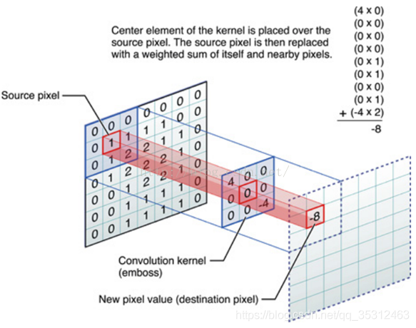
可具体学习此网站学习常用卷积对图形的处理。
二、实现
2.1 常规创建
首先,我们需要定义图形和计算管线的数据结构体:
	// 图形部分的资源
	struct {
		VkDescriptorSetLayout descriptorSetLayout;	// 图像显示着色器绑定布局
		VkDescriptorSet descriptorSetPreCompute;	// 图像显示着色器绑定之前,计算着色器图像操作
		VkDescriptorSet descriptorSetPostCompute;	// 图像显示着色器绑定后,计算着色器图像操作
		VkPipeline pipeline;						// 图像显示管道
		VkPipelineLayout pipelineLayout;			// 图形管线的布局
	} graphics;

	// 计算部分的资源
	struct Compute {
		VkQueue queue;								// 用于计算命令的独立队列(队列族可能不同于用于图形的队列)
		VkCommandPool commandPool;					// 使用单独的命令池(队列族可能不同于用于图形的命令池)
		VkCommandBuffer commandBuffer;				// 存储调度命令和屏障的命令缓冲区
		VkFence fence;								// 同步围栏,以避免重写计算CB如果仍在使用
		VkDescriptorSetLayout descriptorSetLayout;	// 计算着色绑定布局
		VkDescriptorSet descriptorSet;				// 计算着色器绑定
		VkPipelineLayout pipelineLayout;			// 计算管道的布局
		std::vector<VkPipeline> pipelines;			// 为图像过滤器计算管道
		int32_t pipelineIndex = 0;					// 当前图像滤波计算流水线索引
		uint32_t queueFamilyIndex;					// 图形队列的族索引,用于屏障
	} compute;
之后,我们需要创建一个函数prepareTextureTarget来准备一个用于存储计算着色器计算的纹理目标:
	void prepareTextureTarget(vks::Texture *tex, uint32_t width, uint32_t height, VkFormat format)
	{
		VkFormatProperties formatProperties;

		// 获取请求的纹理格式的设备属性
		vkGetPhysicalDeviceFormatProperties(physicalDevice, format, &formatProperties);
		// 检查所请求的图像格式是否支持图像存储操作
		assert(formatProperties.optimalTilingFeatures & VK_FORMAT_FEATURE_STORAGE_IMAGE_BIT);

		// 准备目标纹理宽高
		tex->width = width;
		tex->height = height;

		VkImageCreateInfo imageCreateInfo = vks::initializers::imageCreateInfo();
		imageCreateInfo.imageType = VK_IMAGE_TYPE_2D;
		imageCreateInfo.format = format;
		imageCreateInfo.extent = { width, height, 1 };
		imageCreateInfo.mipLevels = 1;
		imageCreateInfo.arrayLayers = 1;
		imageCreateInfo.samples = VK_SAMPLE_COUNT_1_BIT;
		imageCreateInfo.tiling = VK_IMAGE_TILING_OPTIMAL;
		// 图像将在片段着色器中采样,并在计算着色器中用作存储目标
		imageCreateInfo.usage = VK_IMAGE_USAGE_SAMPLED_BIT | VK_IMAGE_USAGE_STORAGE_BIT;
		imageCreateInfo.flags = 0;
		// 共享模式独占意味着不需要在计算队列和图形队列之间显式地转移映像的所有权
		imageCreateInfo.sharingMode = VK_SHARING_MODE_EXCLUSIVE;

		VkMemoryAllocateInfo memAllocInfo = vks::initializers::memoryAllocateInfo();
		VkMemoryRequirements memReqs;

		VK_CHECK_RESULT(vkCreateImage(device, &imageCreateInfo, nullptr, &tex->image));

		vkGetImageMemoryRequirements(device, tex->image, &memReqs);
		memAllocInfo.allocationSize = memReqs.size;
		memAllocInfo.memoryTypeIndex = vulkanDevice->getMemoryType(memReqs.memoryTypeBits, VK_MEMORY_PROPERTY_DEVICE_LOCAL_BIT);
		VK_CHECK_RESULT(vkAllocateMemory(device, &memAllocInfo, nullptr, &tex->deviceMemory));
		VK_CHECK_RESULT(vkBindImageMemory(device, tex->image, tex->deviceMemory, 0));

		VkCommandBuffer layoutCmd = vulkanDevice->createCommandBuffer(VK_COMMAND_BUFFER_LEVEL_PRIMARY, true);

		tex->imageLayout = VK_IMAGE_LAYOUT_GENERAL;
		vks::tools::setImageLayout(
			layoutCmd, tex->image,
			VK_IMAGE_ASPECT_COLOR_BIT,
			VK_IMAGE_LAYOUT_UNDEFINED,
			tex->imageLayout);

		vulkanDevice->flushCommandBuffer(layoutCmd, queue, true);

		// 创建取样器
		VkSamplerCreateInfo sampler = vks::initializers::samplerCreateInfo();
		sampler.magFilter = VK_FILTER_LINEAR;
		sampler.minFilter = VK_FILTER_LINEAR;
		sampler.mipmapMode = VK_SAMPLER_MIPMAP_MODE_LINEAR;
		sampler.addressModeU = VK_SAMPLER_ADDRESS_MODE_CLAMP_TO_BORDER;
		sampler.addressModeV = sampler.addressModeU;
		sampler.addressModeW = sampler.addressModeU;
		sampler.mipLodBias = 0.0f;
		sampler.maxAnisotropy = 1.0f;
		sampler.compareOp = VK_COMPARE_OP_NEVER;
		sampler.minLod = 0.0f;
		sampler.maxLod = tex->mipLevels;
		sampler.borderColor = VK_BORDER_COLOR_FLOAT_OPAQUE_WHITE;
		VK_CHECK_RESULT(vkCreateSampler(device, &sampler, nullptr, &tex->sampler));

		// 创建图像视图
		VkImageViewCreateInfo view = vks::initializers::imageViewCreateInfo();
		view.image = VK_NULL_HANDLE;
		view.viewType = VK_IMAGE_VIEW_TYPE_2D;
		view.format = format;
		view.components = { VK_COMPONENT_SWIZZLE_R, VK_COMPONENT_SWIZZLE_G, VK_COMPONENT_SWIZZLE_B, VK_COMPONENT_SWIZZLE_A };
		view.subresourceRange = { VK_IMAGE_ASPECT_COLOR_BIT, 0, 1, 0, 1 };
		view.image = tex->image;
		VK_CHECK_RESULT(vkCreateImageView(device, &view, nullptr, &tex->view));

		// 初始化描述符供以后使用
		tex->descriptor.imageLayout = tex->imageLayout;
		tex->descriptor.imageView = tex->view;
		tex->descriptor.sampler = tex->sampler;
		tex->device = vulkanDevice;
	}
接下来,我们正常创建一个图形管线来渲染一个正方形即可。其中用于显示的顶点及片元着色器很简单,仅是用到了一个纹理贴图如下:
顶点着色器:
#version 450

layout (location = 0) in vec3 inPos;
layout (location = 1) in vec2 inUV;

layout (binding = 0) uniform UBO
{
	mat4 projection;
	mat4 model;
} ubo;

layout (location = 0) out vec2 outUV;

out gl_PerVertex
{
	vec4 gl_Position;
};

void main()
{
	outUV = inUV;
	gl_Position = ubo.projection * ubo.model * vec4(inPos.xyz, 1.0);
}
片元着色器:
#version 450

layout (binding = 1) uniform sampler2D samplerColor;

layout (location = 0) in vec2 inUV;

layout (location = 0) out vec4 outFragColor;

void main()
{
  outFragColor = texture(samplerColor, inUV);
}
其中,应注意在创建描述符池的时候,我们应加入一个用于计算管道使用存储映像进行映像读写的描述符池:
	void setupDescriptorPool()
	{
		std::vector<VkDescriptorPoolSize>poolSizes = {
			// 图形管线统一缓冲区
			vks::initializers::descriptorPoolSize(VK_DESCRIPTOR_TYPE_UNIFORM_BUFFER, 2),
			// 图形管线图像采样器显示计算输出图像
			vks::initializers::descriptorPoolSize(VK_DESCRIPTOR_TYPE_COMBINED_IMAGE_SAMPLER, 2),
			// 计算管道使用存储映像进行映像读写
			vks::initializers::descriptorPoolSize(VK_DESCRIPTOR_TYPE_STORAGE_IMAGE, 2),
		};
		VkDescriptorPoolCreateInfo descriptorPoolInfo = vks::initializers::descriptorPoolCreateInfo(poolSizes, 3);
		VK_CHECK_RESULT(vkCreateDescriptorPool(device, &descriptorPoolInfo, nullptr, &descriptorPool));
	}
在创建描述符集的时候我们也要对应的使用vkAllocateDescriptorSets函数分配输入图像(计算后处理前)和最终图像(经过计算着色处理后)两个描述符集对象并更新。
2.2 计算着色器与单独的计算队列
最后重点来了!!!!创建计算着色器与单独的计算队列。
首先,我们需要查找并创建一个可计算的设备队列:
	// 查找并创建一个可计算的设备队列
	void getComputeQueue()
	{
		uint32_t queueFamilyCount;
		vkGetPhysicalDeviceQueueFamilyProperties(physicalDevice, &queueFamilyCount, NULL);
		assert(queueFamilyCount >= 1);

		std::vector<VkQueueFamilyProperties> queueFamilyProperties;
		queueFamilyProperties.resize(queueFamilyCount);
		vkGetPhysicalDeviceQueueFamilyProperties(physicalDevice, &queueFamilyCount, queueFamilyProperties.data());

		//一些设备有专门的计算队列,因此我们首先尝试找到一个支持计算而不支持图形的队列
		bool computeQueueFound = false;
		for (uint32_t i = 0; i < static_cast<uint32_t>(queueFamilyProperties.size()); i++)
		{
			if ((queueFamilyProperties[i].queueFlags & VK_QUEUE_COMPUTE_BIT) && ((queueFamilyProperties[i].queueFlags & VK_QUEUE_GRAPHICS_BIT) == 0))
			{
				compute.queueFamilyIndex = i;
				computeQueueFound = true;
				break;
			}
		}

		//如果没有专用的计算队列,只需找到支持计算的第一个队列族即可
		if (!computeQueueFound)
		{
			for (uint32_t i = 0; i < static_cast<uint32_t>(queueFamilyProperties.size()); i++)
			{
				if (queueFamilyProperties[i].queueFlags & VK_QUEUE_COMPUTE_BIT)
				{
					compute.queueFamilyIndex = i;
					computeQueueFound = true;
					break;
				}
			}
		}

		// 计算在Vulkan中是必需的,因此必须至少有一个队列家族支持计算
		assert(computeQueueFound);
		// 从设备获取一个计算队列
		vkGetDeviceQueue(device, compute.queueFamilyIndex, 0, &compute.queue);
	}
再次,我们来创建计算管线相关,在描述符布局中我们绑定输入和输出两个位置:
	std::vector<VkDescriptorSetLayoutBinding> setLayoutBindings = {
			// Binding 0: Input image (read-only) 输入图像(只读)
			vks::initializers::descriptorSetLayoutBinding(VK_DESCRIPTOR_TYPE_STORAGE_IMAGE, VK_SHADER_STAGE_COMPUTE_BIT, 0),
			// Binding 1: Output image (write) 输出图像(写)
			vks::initializers::descriptorSetLayoutBinding(VK_DESCRIPTOR_TYPE_STORAGE_IMAGE, VK_SHADER_STAGE_COMPUTE_BIT, 1),
		};
创建描述符布局,管线布局,描述符分配等基本步骤不再累述…
接下来,我们根据之前的这些布局数据,创建一个边缘检测卷积计算着色器,其着色器如下:
#version 450

layout (local_size_x = 16, local_size_y = 16) in;
layout (binding = 0, rgba8) uniform readonly image2D inputImage;
layout (binding = 1, rgba8) uniform image2D resultImage;

float conv(in float[9] kernel, in float[9] data, in float denom, in float offset)
{
   float res = 0.0;
   for (int i=0; i<9; ++i)
   {
      res += kernel[i] * data[i];
   }
   return clamp(res/denom + offset, 0.0, 1.0);
}

struct ImageData
{
	float avg[9];
} imageData;

void main()
{
	// 取相邻的像素数据
	int n = -1;
	for (int i=-1; i<2; ++i)
	{
		for(int j=-1; j<2; ++j)
		{
			n++;
			vec3 rgb = imageLoad(inputImage, ivec2(gl_GlobalInvocationID.x + i, gl_GlobalInvocationID.y + j)).rgb;
			imageData.avg[n] = (rgb.r + rgb.g + rgb.b) / 3.0;
		}
	}

	float[9] kernel;
	kernel[0] = -1.0; kernel[1] =  0.0; kernel[2] =  0.0;
	kernel[3] = 0.0; kernel[4] = -1.0; kernel[5] =  0.0;
	kernel[6] = 0.0; kernel[7] =  0.0; kernel[8] = 2.0;

	vec4 res = vec4(vec3(conv(kernel, imageData.avg, 1.0, 0.50)), 1.0);

	imageStore(resultImage, ivec2(gl_GlobalInvocationID.xy), res);
}
记载此着色器,并创建对应的计算管线:
	//创建计算着色器管道
	std::string fileName = getAssetPath() + "shaders/computeshader/edgedetect.comp.spv";
	computePipelineCreateInfo.stage = loadShader(fileName, VK_SHADER_STAGE_COMPUTE_BIT);
	VkPipeline pipeline;
	VK_CHECK_RESULT(vkCreateComputePipelines(device, pipelineCache, 1, &computePipelineCreateInfo, nullptr, &pipeline));
之后,便是常规操作:我们需要创建单独的命令池作为计算的队列族,并且为这个计算管线为计算操作创建一个命令缓冲区,然后创建一个栅栏用于同步计算。
最后,我们还要构建一个buildComputeCommandBuffer函数包含计算调度命令的命令缓冲区(类似常规的buildCommandBuffer)。
	void buildComputeCommandBuffer()
	{
		//如果我们在管道更改后重新构建命令缓冲区以确保它当前未被使用,则刷新队列
		vkQueueWaitIdle(compute.queue);

		VkCommandBufferBeginInfo cmdBufInfo = vks::initializers::commandBufferBeginInfo();

		VK_CHECK_RESULT(vkBeginCommandBuffer(compute.commandBuffer, &cmdBufInfo));

		vkCmdBindPipeline(compute.commandBuffer, VK_PIPELINE_BIND_POINT_COMPUTE, compute.pipelines[compute.pipelineIndex]);
		vkCmdBindDescriptorSets(compute.commandBuffer, VK_PIPELINE_BIND_POINT_COMPUTE, compute.pipelineLayout, 0, 1, &compute.descriptorSet, 0, 0);

		vkCmdDispatch(compute.commandBuffer, textureComputeTarget.width / 16, textureComputeTarget.height / 16, 1);

		vkEndCommandBuffer(compute.commandBuffer);
	}
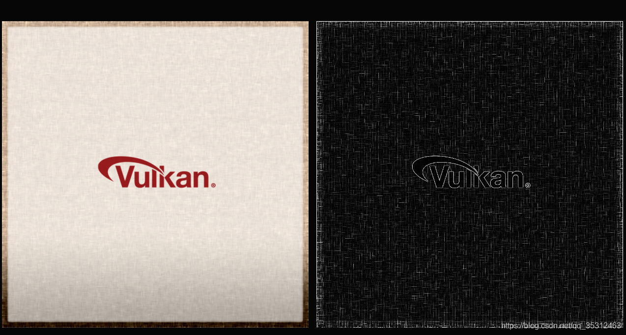
运行着色器,可以看到下图效果:
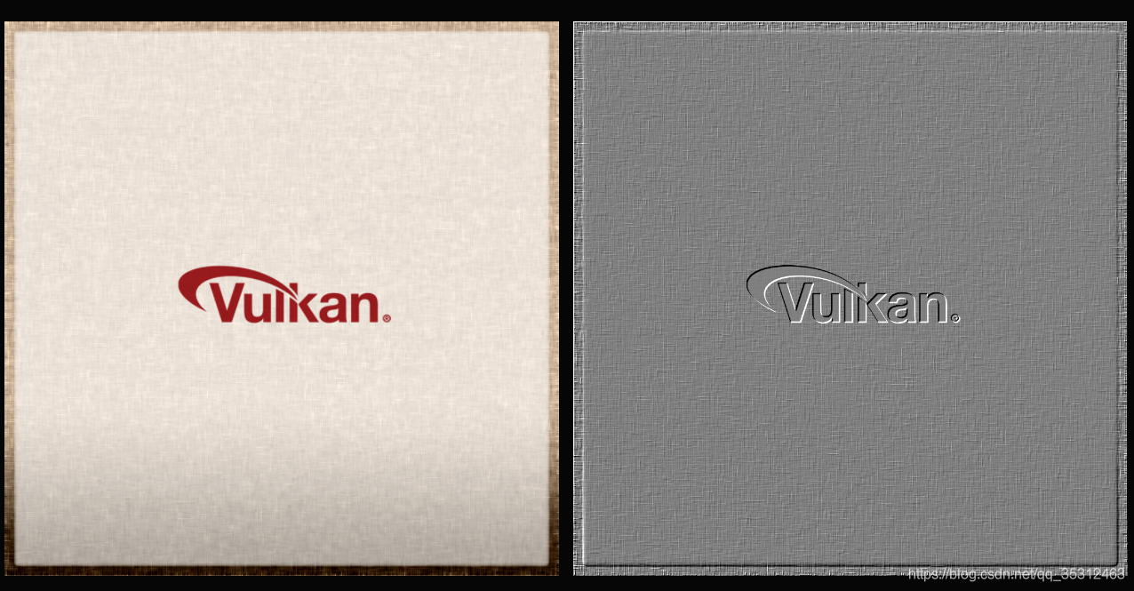
再比如,我们使用浮雕卷积,修改计算着色器代码:
	float[9] kernel;
	kernel[0] = -1.0; kernel[1] =  0.0; kernel[2] =  0.0;
	kernel[3] = 0.0; kernel[4] = -1.0; kernel[5] =  0.0;
	kernel[6] = 0.0; kernel[7] =  0.0; kernel[8] = 2.0;
编译着色器运行,可见:
版权声明:本文为博主 沉默的舞台剧 原创文章,
遵循 CC 4.0 BY-SA 版权协议,转载请附上原文出处链接和本声明。
原文链接:https://blog.csdn.net/qq_35312463/article/details/106029755